The Electronic Components
It’s important to understand that the Launch Control System is really that – a collection of individual components combined into a single, cohesive system. Let’s look at the various elements used in the system.
Display
When I first started thinking about this project I knew I wanted it to have weather sensors available. However, the sensors would be useless on the field unless we had a way to review their data in real time. So a display was an absolute requirement.
LCD Screen

The obvious choice for me was to use a LCD screen to display that data. Why choose an LCD screen? Was it the ease of use? Was it the cool blue color? Was it the ???? Nope, nope, nope, nope, nope. The reason was more basic. I had one on hand. It was included in my starter kit, I had used it in one of the tutorials, and so I was familiar with it.
The reason I bring this up is that you should feel free to use what equipment and parts you have on hand. Don’t feel you have to use the exact same parts I used. At the end of this series I’ll discuss what I learned, including better alternatives to some of the components I used. Expand yourself by trying new things (or reusing old things if appropriate). Experiment. It’s fun.
The LCD screen that came in the starter kit is an Elegoo LCD1602 module. It is also the component that uses the most pins on the Arduino – six (pins D7 through D12). That is actually half of the available digital pins (yes, there are 14 digital pins but pins 0 and 1 are used for serial communication. Given you have to use a USB – Universal Serial Bus – cable to upload your code as well as view the sensor data in the Serial Monitor, they are not available). In addition, the LCD screen uses two +5V connections and two grounds, plus another connection for the potentiometer that adjust the contrast on the screen. Other than the 5V connection (which is shared with the other components) none of the additional pins on the LCD are used.
LED Clock
 The next display I wanted to add was a LED clock. This is a 4-digit, 7-segment display that has the primary job of displaying the current time. I also use it to display the 10-second countdown as well as other simple messages. It uses two of the digital pins on the Arduino (D4 and D5) and requires a +5V and ground connection.
Sensors
With the display taken care of it was time to look at the sensors. This included the humidity, temperature and pressure sensors.
DHT11 Temperature and Humidity Sensor
 I selected the DHT11 sensor because I had one that came in my starter kit. This sensor only uses one pin on the Arduino (A2). Like the other components we have talked about it also needs a 5V and ground connection.
BMP180 Pressure and Temperature Sensor
This was another component I also had on hand. This sensor measures atmospheric pressure and temperature which can be used to measure altitude. In this case I was only interested in the pressure readings.
 The BMP180 uses two of the analog pins on the Arduino (A4 and A5). These pins are used for I2C communication. The advantage of I2C is that multiple components can share the same two pins provided the components all have different addresses. Given the limited number of pins on the Arduino, I2C allows you to add additional components (such as the Real Time Clock listed below) without using additional pins.
The BMP180 is also different from the other components we have talked about when it comes to power. It requires +3.3V and a ground. If you supply the sensor with +5V you will burn up the sensor.
Buttons and Switches
On the launch system there are four buttons, two switches and one potentiometer. Lets look at each one and what they do.
Arduino Power Button
 There is a push button that provides power to the Arduino. This switch is inserted between the positive terminal of the 9-volt battery and VIN (Voltage In) pin on the Arduino. It also uses a ground connection.
Arduino Reset Button
This is a momentary push button that when pushed will reset the system. It will cause the system to reboot and go through the initialization process. It is connected to the RST (reset) pin on the Arduino.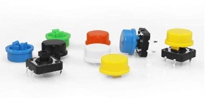
LCD Screen Selection Button
This is another momentary push button that is used to scroll through the various information screens on the LCD display. It allows you to select the Date/Time screen, the temperature and humidity screen, the atmospheric pressure screens, and the launch system volt meter. It is attached to pin D3 on the Arduino.
Key Switch
 This switch is between the launch pad battery and the relay. It also splits to the continuity lamp as well. This switch has a removable key. This allows the user to turn the launch pad power system off, remove the key, and not have to worry about the system being powered back on. The key switch is a critical safety component of the system.
Fire Button
The red button is the primary button that provides the signal to send power to the launch pad. It is connected to pin D2 (as well as ground) on the Arduino. However, pressing the Fire button alone will not start the countdown. It needs to be used in conjunction with the Safety button.

Safety Button
As noted in the name, this button is used to make sure that the countdown is not started accidentally. Similar to the Fire button, it is black and is connected to a single pin (as well as ground) on the Arduino. In this case it is connected to pin D6.
LCD Screen Potentiometer
 The potentiometer is used to adjust the contrast on the LCD screen. This allows you to get the best view of the messages being displayed whether you are inside or outside. The potentiometer has three connections, but does not use a single pin on the Arduino. It needs +5V and ground, while the 3rd (middle) pin is connected to the LCD screen (V0 – screen contrast).
While not technically a switch or button (it is actually a variable resistor), its use as an input is more closely related to the components in this section which is why I included it here.
Notification and Warning Devices
In addition to the LCD screen and 4-digit 7-segment clock, the system has two LED lamps and a piezo buzzer to let the user know if the system is working properly or if events are occurring.
Arduino Power LED
 The first LED lamp will light up green if the Arduino is powered up. This lamp is connected to pin D13 and ground. As with most LEDs, a resistor was added to reduce the current flow to the LED. Here we used a 510Ω (ohm) resistor.
The lamp doesn’t indicate the presence of power to the system, but rather that the Arduino itself has power and is on. If the Arduino power button is pressed and the light doesn’t come on, you need to start checking your power supply, and if it is good, the power connections to the Arduino.
Continuity LED Lamp
 The second LED lamp will light up red once the key switch has been turned on and there is a complete circuit out to the launch pad. This includes the igniter in the model rocket engine. If the igniter is bad, not connected properly, or shorting out against the launch rod or blast deflector, the continuity lamp will not come on. This lamp does not use any pins on the Arduino. Instead it sits between the key switch and the igniter clip at the pad.
A resistor was added here as well for two reasons. Like the Arduino power LED, I need to reduce the power flow to the LED itself to prevent it from burning out. However, I also need to reduce the power flow to the igniter to prevent it from igniting prematurely. Here I chose a 1000Ω resistor.
Piezo Buzzer
 The piezo buzzer is used to help draw your attention to certain activities occurring on the system. It will chirp when the system successfully initializes, it provides warnings that a countdown is underway on each second as well as a long continuous tone while power is being supplied to the launch pad. It also chirps rapidly and repeatedly when a launch is aborted.
Real Time Clock
 I wanted a Real Time Clock (RTC) included in this project to provide an accurate date and time stamp for the data. The RTC will sync the date and time to the local computer. It has its own battery which keeps the clock running even when power to the system is turned off.
Like the BMP180, the RTC uses I2C and so it shares the use of pins A4 and A5. Unlike the BMP180, the RTC makes use of the +5V power connection and ground.
Firing Relay
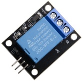 The firing relay takes the signal from the Arduino and allows power to continue to the launch pad. It is the gate keeper for the launch pad power. Like the other components is uses +5V and ground. It also uses a single pin on the Arduino (A3).
On the opposite side of the relay the positive power coming off of the Key Switch. This is attached to the Common (middle) connection. A second line comes off the relay on the Normally Open (NO) connection and goes to the igniter clip at the pad.
Launch Pad Power Sensor
When I started this project I decided to make my own little sensor called a voltage divider. It is basically two resistors connected in series, with a sensor wire located between the two resistors. The power for the meter comes off of the Common Feed on the relay and it needs a ground wire. The sensor wire was routed to pin A0.
We had issues with this sensor and I will go into more detail on the sensor and the issues in a later post. Beginning with hardware revision 7.1 it was disconnected from the system.
The Arduino Boards
I used two Arduino boards during the development and building of the project. This included the Arduino Uno and the Arduino Nano.
Arduino Uno
 The Uno board was used during the initial development of the system. This board makes it easy to attach jumper wires between the Uno board, a breadboard, and the various components. This also helps with rapid testing of various aspects of the system as well as moving connections and components as needed.
Arduino Nano
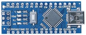 The Nano board is used during the actual construction of the launch system. The Nano has all of the same pins as the Uno (It actually has two additional pins that we didn’t use) and the code is interchangeable between the two devices (provided the two additional pins on the Nano are not referenced). The Nano board is considerably smaller than the Uno board and this provided various positioning options during the initial work on the layout of the components in the project box. It also allows room for additional components in the future if desired.
Working Together to Start the Countdown
There are a number of components used to actually fire the rocket. In order for the countdown to start and power to be supplied to the launch pad, several things must be in place. First, the power must be turned on to the Arduino. The system will not fire without the Arduino being powered up, as it reads the signals from the fire and safety buttons, as well as sends the signal to the relay.
Second, the key switch must have the key inserted and turned on. Without the key, the switch will not turn on. Without the switch being turned on, power will not flow from the launch battery to the relay and on to the launch pad.
Finally we come to the Fire and Safety buttons. To start the countdown both buttons must be pressed down. Additionally, they must remain pressed down during the countdown. If either button is released, the countdown will stop and the launch is aborted.
The use of the key switch and the double buttons brings an added layer of safety into the system to help prevent accidental launches.
So now you have a listing of all the electrical components (except for wires and resistors) I used in this project. In the next post I’ll start on how I developed the breadboard prototype.
